
USB C Cable 240W: EPR and E-Marker Check
Verify a USB-C cable for Extended Power Range charging using cable power logos, E-Marker Discover Identity fields, and phone charging rules.

Verify the cable power logo, E-Marker identity fields and device charging rules across the charger, cable and sink.
The USB Type-C receptacle is specified for a current capability of 5 A, whereas standard USB Type-C cable assemblies are rated for 3 A. USB Type-C cable assemblies designed for USB PD and identified via electronic marking are allowed to support up to 5 A. USB Type-C cable assemblies designed for USB PD Extended Power Range (EPR) operation are required to be electronically marked for 5 A and 50 V and include the EPR Mode Capable bit set.
USB PD Revision 3.1 enables up to 240W over a full-featured USB Type-C cable (compared to the prior 100W limit at 20V on 5A cables) and adds 28V, 36V, and 48V fixed voltages for up to 140W, 180W, and 240W. USB PD 3.1 adds three fixed voltages (28V above 100W, 36V above 140W, and 48V above 180W) joining 5V, 9V, 15V, and 20V, plus an adjustable voltage mode from 15V to 28V, 36V, or 48V at a 100 mV resolution. Existing USB PD SPR 5 A cables have been deprecated and replaced by USB PD EPR cables, and cables that are full-featured or rated at more than 3 A current are Electronically Marked Cables.
Compare cable reference classes and voltage tiers
Review the Charging & Power category and our Android charging guide when matching adapters, cables and portable devices across power tiers.
Scroll horizontally to see all columns.
| Assembly class | Specification reference | Selection check |
|---|---|---|
| Basic charging assembly | In Table 3-1, USB 2.0 C-to-C cable reference CC2-3 has a 3A current rating, supports USB Power Delivery (SPR Only), and has Optional electronic marking. | Treat unmarked cords as lower-current assemblies restricted to the lower voltage range. |
| Extended power charging cord | In Table 3-1, USB 2.0 C-to-C cable reference CC2-5E has an informative length of ≤ 4 m, a 5A current rating, supports USB Power Delivery (SPR & EPR), and has Required electronic marking. | Use this marked cord class when you need long span with full-range power delivery. |
| Entry high-speed assembly | In Table 3-1, USB 3.2 Gen1 and USB4 Gen2 C-to-C cable reference CC3G1-5E has an informative length of ≤ 2 m, a 5A current rating, supports SPR & EPR, and requires electronic marking. | Check cord length and marking before pairing with an external display or dock. |
| Mid-tier high-speed assembly | In Table 3-1, USB 3.2 Gen2 and USB4 Gen2 C-to-C cable reference CC3G2-5E has an informative length of ≤ 1 m, a 5A current rating, supports SPR & EPR, and requires electronic marking. | Verify shorter cord span when combining fast data lanes with full-range power. |
| Top-tier high-speed assembly | In Table 3-1, USB4 Gen3 and USB4 Gen4 C-to-C cable reference CC4G3-5E has an informative length of ≤ 0.8 m, a 5A current rating, supports SPR & EPR, and requires electronic marking. | Keep high-bandwidth cords short and confirm electronic marking on both plugs. |
VCONN is independent of VBUS and stays within the voltage range of 3.0 to 5.5 V to power circuits in the plug needed for Electronically Marked Cables. A 10 nF bypass capacitor (minimum recommended voltage rating of 30 V, 63 V if EPR-capable) is required for the VBUS pin in the full-featured cable at each end of the cable. In Table 3-11 Note 3, a bypass capacitor is not required for the VBUS pin in the USB 2.0 Type-C cable.
Any USB Type-C cable assembly that incorporates electrical components or electronics shall ensure that it tolerate, or be protected from, a VBUS voltage of 21 V under Standard Power Range (SPR) operation, while any USB Type-C cable assembly that incorporates electrical components or electronics that may be powered by VBUS shall ensure that it can functionally tolerate, or be protected from, a VBUS voltage of up to 50.9 V (48 V + 5% + 500 mV) under Extended Power Range (EPR) operation. The Renesas / Dialog EBC10293 240W PD3.2 EPR Design Board achieves 96% efficiency at 240W 48V 5A (230V AC) and 95.3% efficiency at 240W 48V 5A, 115VAC, featuring a USB PD 3.2 EPR 240W 5V to 48V solution with <45mW standby power at 230VAC. EPR cables shall functionally support a reported 50 V and 5 A operation, the minimum functional voltage that a cable shall support is 50.9 V, and electrical components potentially in the path of VBUS (such as bypass capacitors) should be minimally rated for 63 V.
Check the cable E-Marker and Discover Identity fields
Compare connector construction details in our USB-C cable guide before inspecting cable identity registers on a test bench.
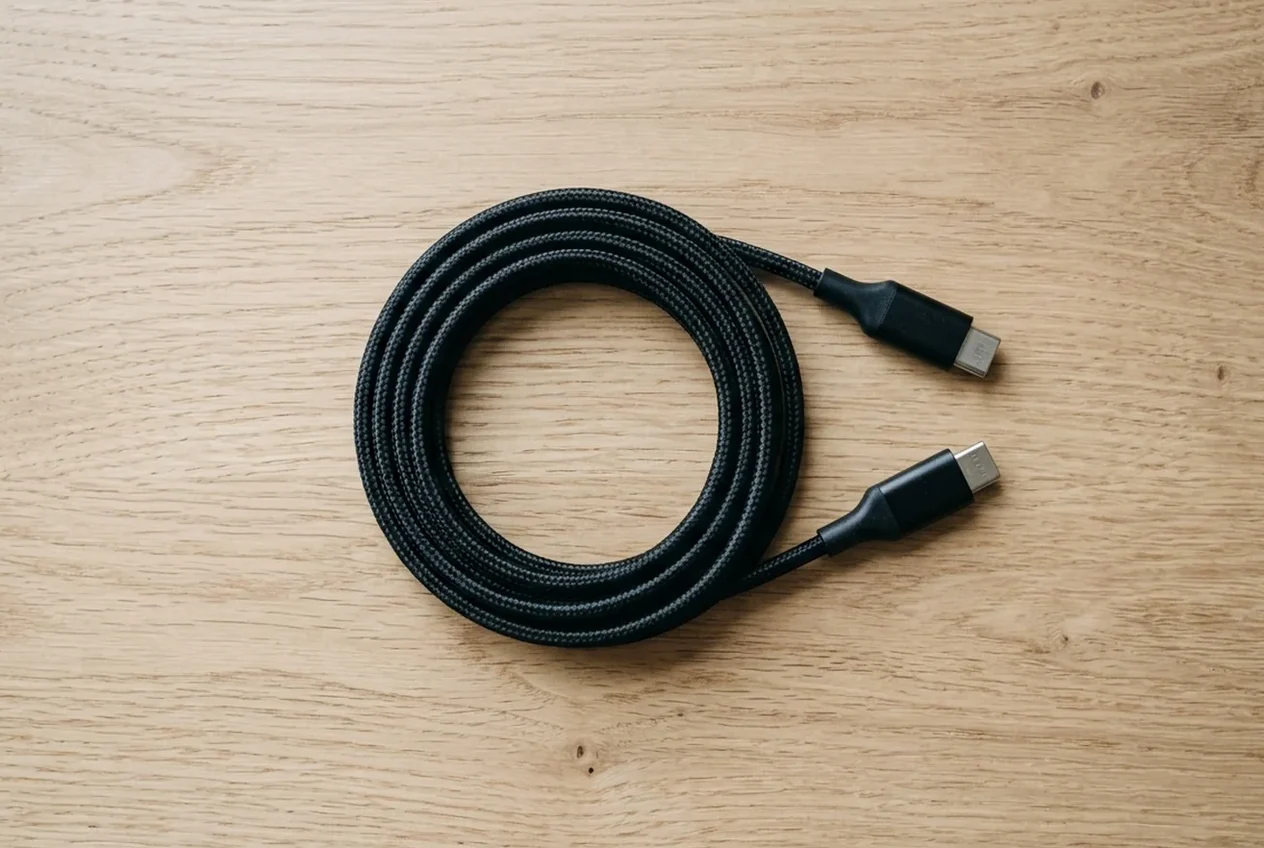
Electronically marked cables shall support the USB Power Delivery Structured VDM Discover Identity command directed to SOP’ (the eMarker), also referred to as the USB Type-C Cable ID function. Under USB PD R3.2 Section 3.2.2 and Section 3.2.3, when Port Maximum PDP or Port Present PDP would be > 60W and the cable VBUS Current Handling Capability = 3A, the Source Port Shall set Port Present PDP = 60W. When Port Maximum PDP > 100W (EPR Capable) and the Cable is not EPR Capable, the Port Shall set the Port Present PDP ≤ 100W, with margin to 100W (e.g. 95W) allowed for safety standards. A Port Present PDP > 60W requires a 5A cable, and for the 20V SPR Fixed PDO, PDO Maximum Current equals Minimum( Cable Rating, Port Present PDP ÷ Fixed PDO Voltage ).
Support of EPR Mode is Optional; an EPR Capable Port has a Port Maximum PDP > 100W and ≤ 240W, and when the Attached cable is not an EPR Capable cable, an EPR Capable Source Shall only operate in SPR Mode. When operating in EPR Mode, an EPR Source Port with a Port Present PDP ≥ 100W Shall offer 5A in the 20V Fixed PDO, and if it supports PPS, Shall offer the SPR Fixed 20V PDO and PPS 20V Prog APDO up to 100W. EPR Source Capabilities specify 28V Fixed (PDP÷28 for 100 < x ≤ 140), 36V Fixed (PDP÷36 for 140 < x ≤ 180), and 48V Fixed (PDP÷48 for 180 < x ≤ 240), with EPR AVS Max Voltage 28V and Available Current (15-28V) for 100 < x ≤ 140, Max Voltage 36V and Available Current (15-36V) for 140 < x ≤ 180, and Max Voltage 48V and Available Current (15-48V) for 180 < x ≤ 240, each calculated as PDP ÷ AVS voltage (maximum of 5A).
Scroll horizontally to see all columns.
| Identity field | Register definition | Bench check |
|---|---|---|
| Entry failure data code | In Table 6.28 (EPR Mode Data Object), when Action is 04h (Enter Failed), Data field value 01h indicates 'Cable not EPR Capable'. | Log the failure code on a protocol analyzer when a source refuses high-voltage entry. |
| Passive cable capability bit | Passive Cables Shall support the Structured VDM Discover Identity Command, and Passive Cable VDO Bit 17 (EPR Capable) indicates safe operation up to 48 volts at 5 amps (0b = not EPR Capable, 1b = EPR Capable). | Confirm the capability bit is asserted in the responder header before testing high-voltage loads. |
| Voltage handling code | In Passive Cable VDO Maximum VBUS Voltage, 00b is 20V (21.55V absolute maximum) and 11b is 50V, where a Fixed Supply of 48V can be Negotiated (50.9V absolute maximum). | Check the voltage field in the passive cable header to distinguish lower and higher voltage cords. |
| Current handling code | In Passive Cable VDO VBUS Current Handling Capability, 01b indicates 3A, 10b indicates 5A, and 00b or 11b are Invalid (receiver Shall assume 01b (3A)). | Verify the current field reports the higher current code rather than the fallback value. |
| Source entry verification | The Source Shall use the Discover Identity Command to read the cable's e-Marker and verify Maximum VBUS Voltage is 11b (50V), VBUS Current Handling Capability is 10b (5A), and EPR Capable is 1b, or abort EPR Mode Entry and remain in SPR. | Verify all three identity fields together when qualifying a replacement cord for high-power sinks. |
| Legacy marker supply floor | Some PD 2.0 E-Markers certified prior to April 2017 may not operate below 5V (implementers should confirm operation down to 2.75V), and the public product list defaults to products certified within the last 2 years. | Retire older cords whose plug electronics fail to respond at lower supply voltages. |
Understand programmable power and device charging behavior
See our comparison of USB PD vs PPS, our guide to using a laptop USB-C charger for Android, and our slow Android phone charging checklist when diagnosing cross-device adapter sharing.
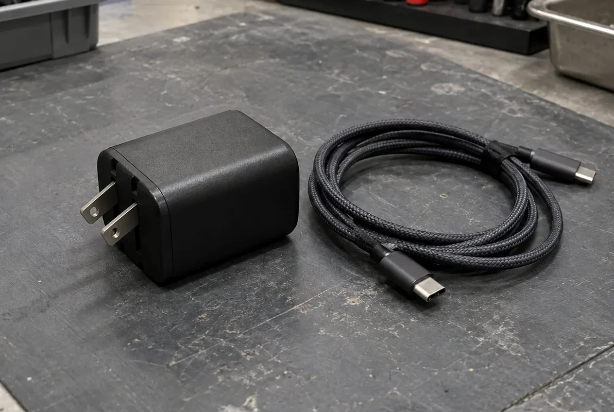
The SPR PPS APDO Maximum Current field Shall Advertise at least 3A, and when the cable VBUS Current Handling Capability = 5A, it May Advertise up to RoundDown( PDP ÷ Prog Voltage ) to the nearest 50mA. Certified USB Fast Chargers support the Programmable Power Supply (PPS) feature of the USB Power Delivery 3.0 specification, and new USB hosts, devices, and chargers supporting PPS are required for the full feature.
Scroll horizontally to see all columns.
| Hardware profile | Documented behavior | Pairing action |
|---|---|---|
| Woven charge cord | Apple's 240W USB-C Charge Cable (2 m) is priced at $29.00, uses a 2-meter woven design with USB-C connectors on both ends, supports charging of up to 240 watts, and transfers data at USB 2 rates. | Use a dedicated charge cord when high power is needed without high-speed data lanes. |
| High-current handset adapters | Samsung Singapore's EP-T4511 (45W), EP-T5020 (50W), and EP-T6530 (65W) chargers support Super fast charging 2.0 based on a 45W, 5A cable, while for Galaxy S25 and later models SFC 2.0 is supported with the included 3A USB cable. | Check whether your handset generation requires a higher-current cord or works with the bundled lead. |
| Mid-power handset adapter | Samsung Singapore's official wired charger table states that EP-T6010 (60W PD charger) outputs PDO 9V, 15V, 20V / 3A and PPS 5–20V / 3A, and supports Super fast charging 3.0 based on a 60W, 3A cable. | Match the adapter programmable output window and cord current tier to the handset specification. |
| Handset adapter guidance | Google recommends a Google 30 W USB-C power adapter or other PPS power adapter rated for 30 W or more, or other USB PD adapters rated for 15 W or more, depending on the Pixel phone. | Confirm programmable power support on the wall adapter before blaming the cord for slow charging. |
Verify cable power logos, data speeds and captive cables
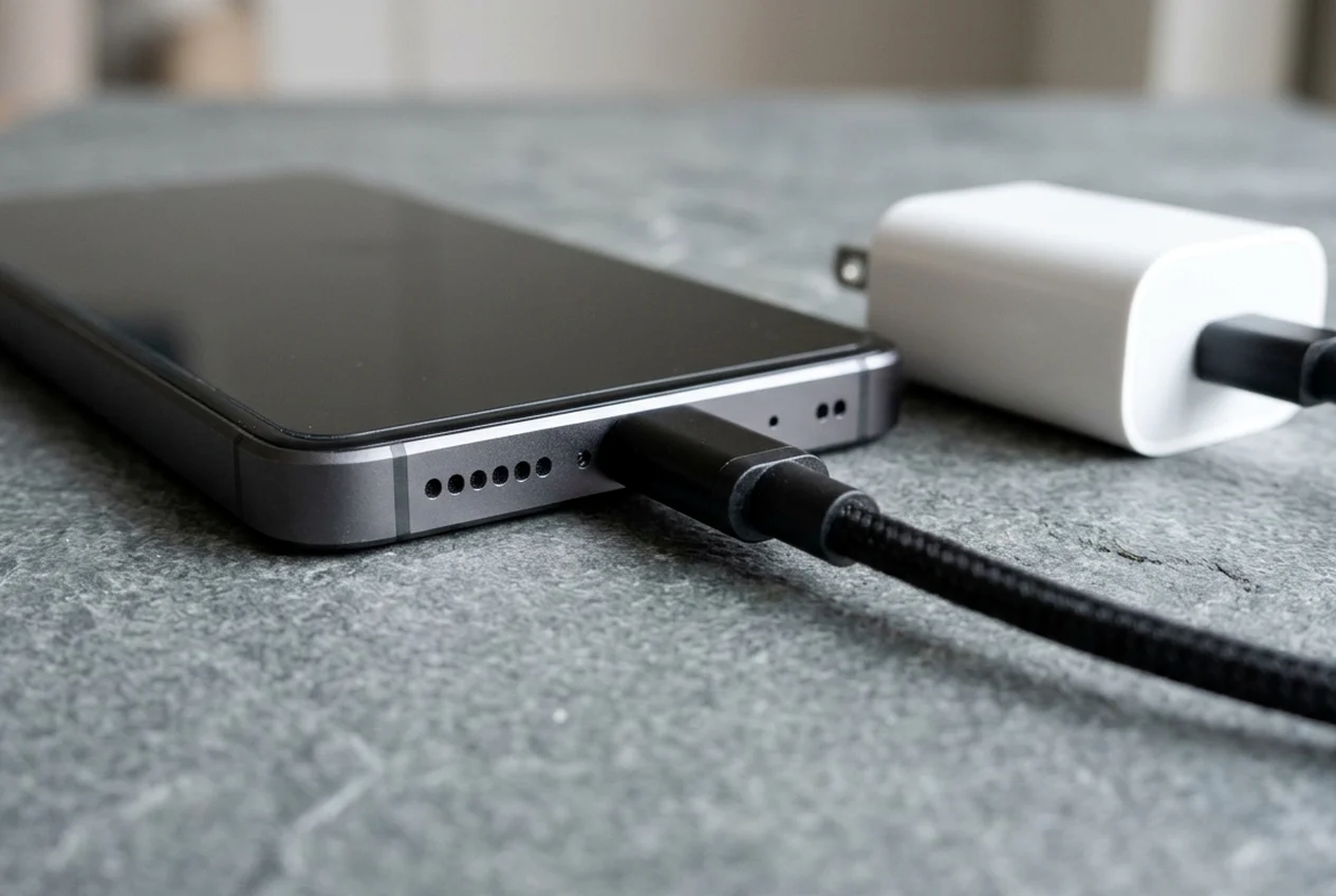
All USB Full-Featured Type-C cable assemblies shall be Electronically Marked and should be certified and visibly identified with certified cable identification icons for power rating (60W or 240W) and data performance (5 Gbps, 20 Gbps or higher). All USB 2.0 Type-C cable assemblies rated for higher than 3A shall be Electronically Marked. All USB 2.0 Type-C cable assemblies should be certified and visibly identified with certified cable identification icons for power rating, either 60W or 240W. To pass through the USB-IF Compliance Program, all USB-C to USB-C cable categories must be labelled with either 60W or 240W power icons/logos, and cables with an E-marker follow the USB Power Delivery Compliance Plan.
- All USB-C to USB-C cables except High-Speed USB (USB 2.0) cables must be marked with their data rate (for example, a USB 20Gbps cable supporting 20V at 3A must carry the 20Gbps/60W logo), while a USB 2.0 cable requires the power icon.
- The USB4 and USB 3.2 specifications together identify five transfer rates (80Gbps, 40Gbps, 20Gbps, 10Gbps, and 5Gbps) with consumer marketing names USB 80Gbps, USB 40Gbps, USB 20Gbps, USB 10Gbps, and USB 5Gbps.
- Under Section 3.4.3, a device (Sink, UFP or DRP) with a captive cable assembly shall respond to SOP’ cable identity inquiries when the device either sinks higher than 3A current or supports USB4 operation.
Frequently asked questions
Does a high-wattage cable increase the charging speed of every connected device?
All cables do not have the same capabilities, and using a certified cable does not eliminate the need for certification of USB products nor does it augment the capabilities of those products.
Do basic charging cables support video output or high-speed data transfer?
A USB 2.0 Type-C to USB 2.0 Type-C cable supports up to 480Mbps data operation and USB Power Delivery, and does not implement TX/RX or Alt-Mode (SBU) signals.
Are permanently attached charger cords eligible for standalone cable logo markings?
Captive cables (having one USB connector and either permanently attached or having a non-USB connector) are not eligible for USB-IF certification, and connectors in a certified cable assembly must have a verified TID.
Record your cable, charger and phone details
- Power logo marking printed on both connector overmolds and retail packaging.
- Electronic marker current and voltage identity fields read on a protocol tester.
- Charger single-port output profile for both fixed and programmable modes.
- Target device charging protocol and required cord current tier.
- Required data transfer signaling speed and display output support.
Sources
- USB Type-C Cable and Connector Specification — USB Implementers Forum
- USB Power Delivery Specification — USB Implementers Forum
- USB-IF Cable Power Capability Logos and Integrators List Guidance — USB Implementers Forum
- Extended Power Range Architecture Technical Reference — Electronic Design
- Fast Charge Technical Support Documentation — Apple Support
- Super Fast Charging Adapter and Cable Support Guide — Samsung Support
- Pixel Phone Charging Adapter and Cable Support Guide — Google Help
- Extended Power Range Reference Design Documentation — Renesas Electronics
Related articles
What Is a GaN Charger and Does It Work With Android?
GaN is the semiconductor in the adapter. PPS is a USB PD 3.0 feature. A 60 W or 240 W mark on a USB-C cable is a cable logo, not the charger rating.
Read article
Can You Use a Laptop USB-C Charger With an Android Phone?
A laptop USB-C wall charger and the laptop USB-C port are different supplies. Compare Dell's 15 W port ceiling, Lenovo 20 V input, PPS, and the 60 W cable logo.
Read article
USB PD vs. PPS: The Android Charging Difference That Matters
PPS is optional inside USB PD 3.0. The phone requests a voltage in 20 mV steps. A 60W or 240W mark is a cable logo.
Read article